
PMPA Craftsman Cribsheet #121:
ISO Turning — What Does it All Mean?
How to make sense of all those different letters and numbers in ISO turning inserts.
Published November 1, 2023
By David Wynn, Technical Services Manager, PMPA
When it comes to ISO turning inserts, there is a lot of confusion about what all those different letters and numbers mean. We have CNMG, TNMG and WNMG. Then there is 432, 332, 434 and more. Even among those who deal with ISO turning inserts everyday, few know what all the different characters mean in relation to the insert. Also, we find that metric and inch standards differ. We discuss inch inserts in this article. Let’s use a CNMG 432 as an example.
CNMG
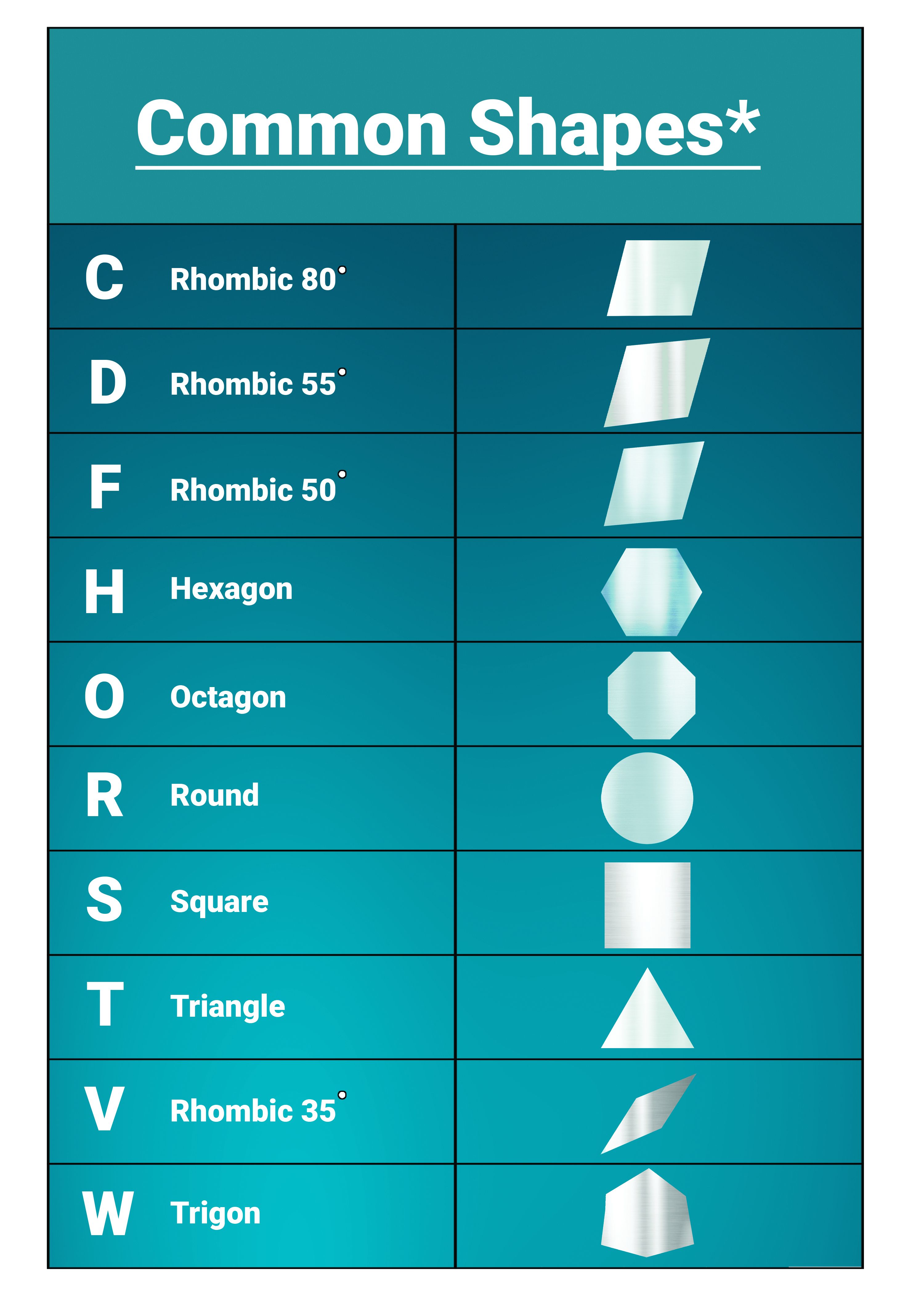
The first letter denotes the shape of the insert. Inserts come in a wide variety of shapes. In this example, “C” is an 80-degree rhombic shape. Other common shapes used in everyday machining include “T” Triangle, “W” Trigon and “V” 35-degrees rhombic.
CNMG
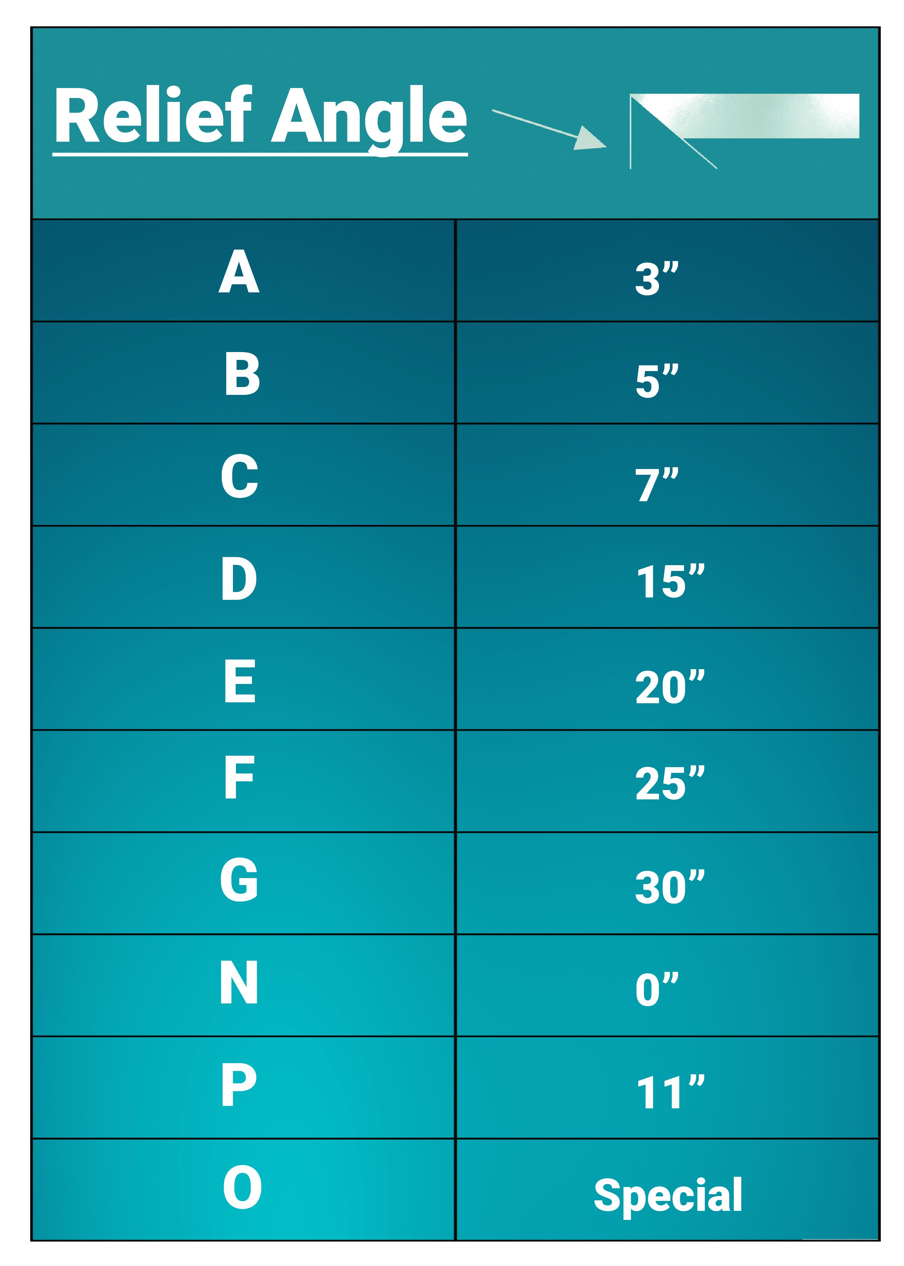
The second letter denotes relief angle. “N” in our example is a 0-degree relief angle. Angles can range from 3-degrees to 30-degrees on standards. Then there is the “O” designation or special angles. For front relief, “C” (7-degrees) is a good common angle for most materials. Some copper grades like to have a little more.
CNMG
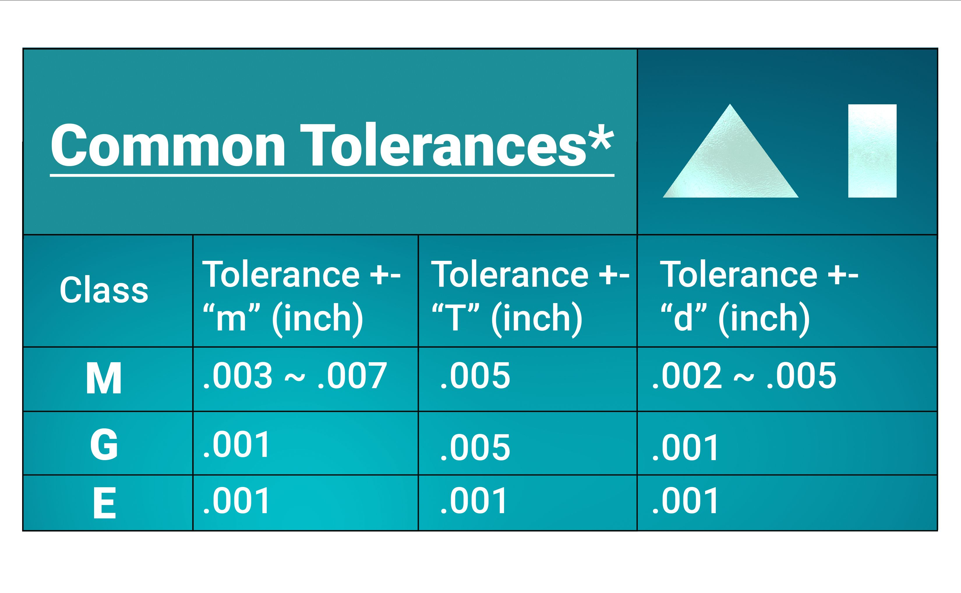
The third letter denotes tolerance level of the insert. The letter “m” is the tolerance of the cutting tip to the inscribed circle. “T” is the insert thickness tolerance. The letter “d” represents the inscribed circle tolerance. “M” is a common tolerance class. “G” is also a common tolerance class, but it comes at a higher cost per insert because of the much better tolerances.
CNMG
The fourth letter denotes fixing and chip breaking. “G” is put in with a screw with no special chamfers on the insert. The chip breaking part was a good idea, but in practice does not really matter.
Most manufacturers make custom or patented chip breakers that have nothing to do with this designation. This letter usually only indicates how the insert attaches to the holder and the back rake design.
The Numbers
432
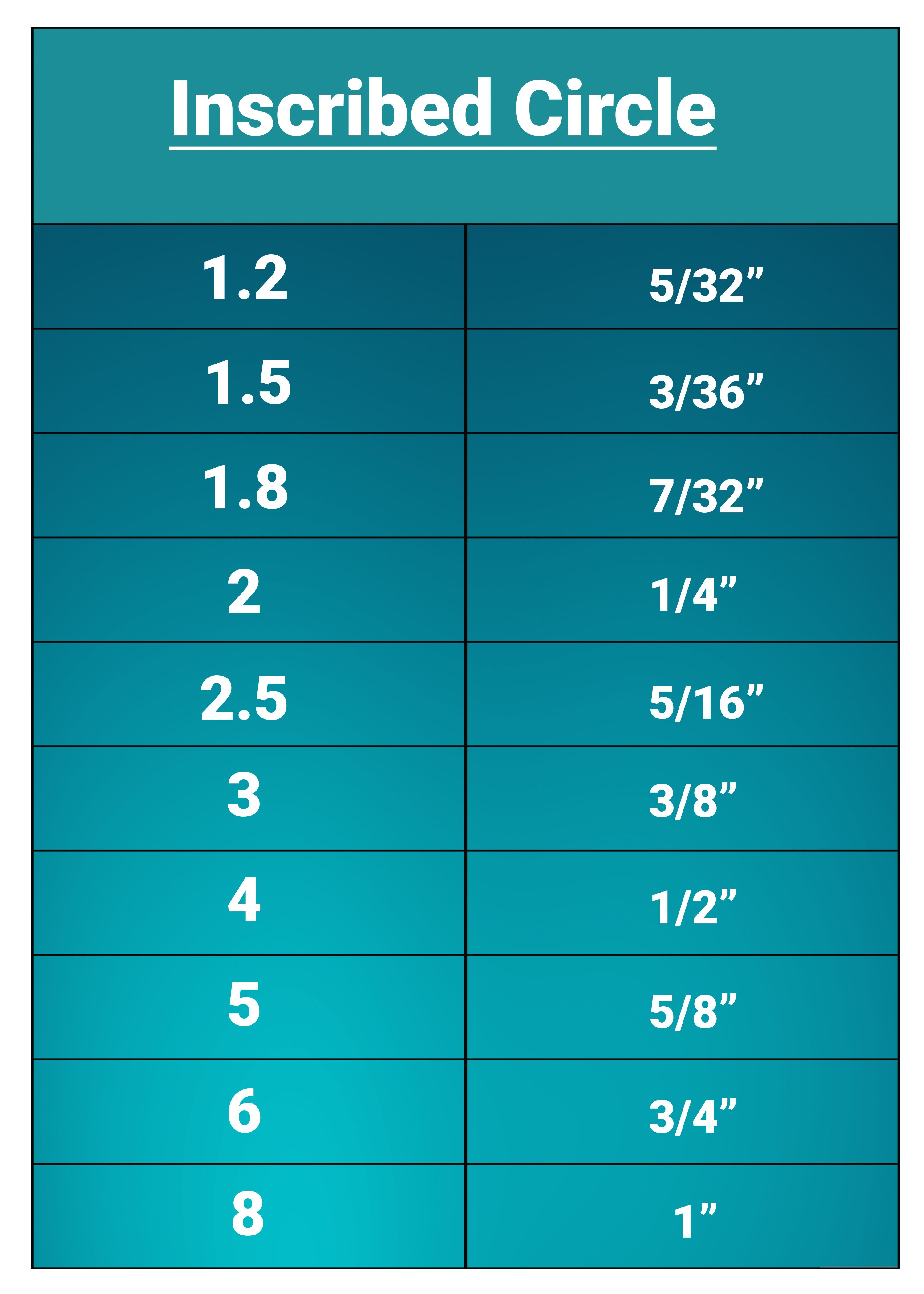
The first number denotes the inscribed circle of the insert. In the example, “4” indicates a 1/2″ inscribed circle.
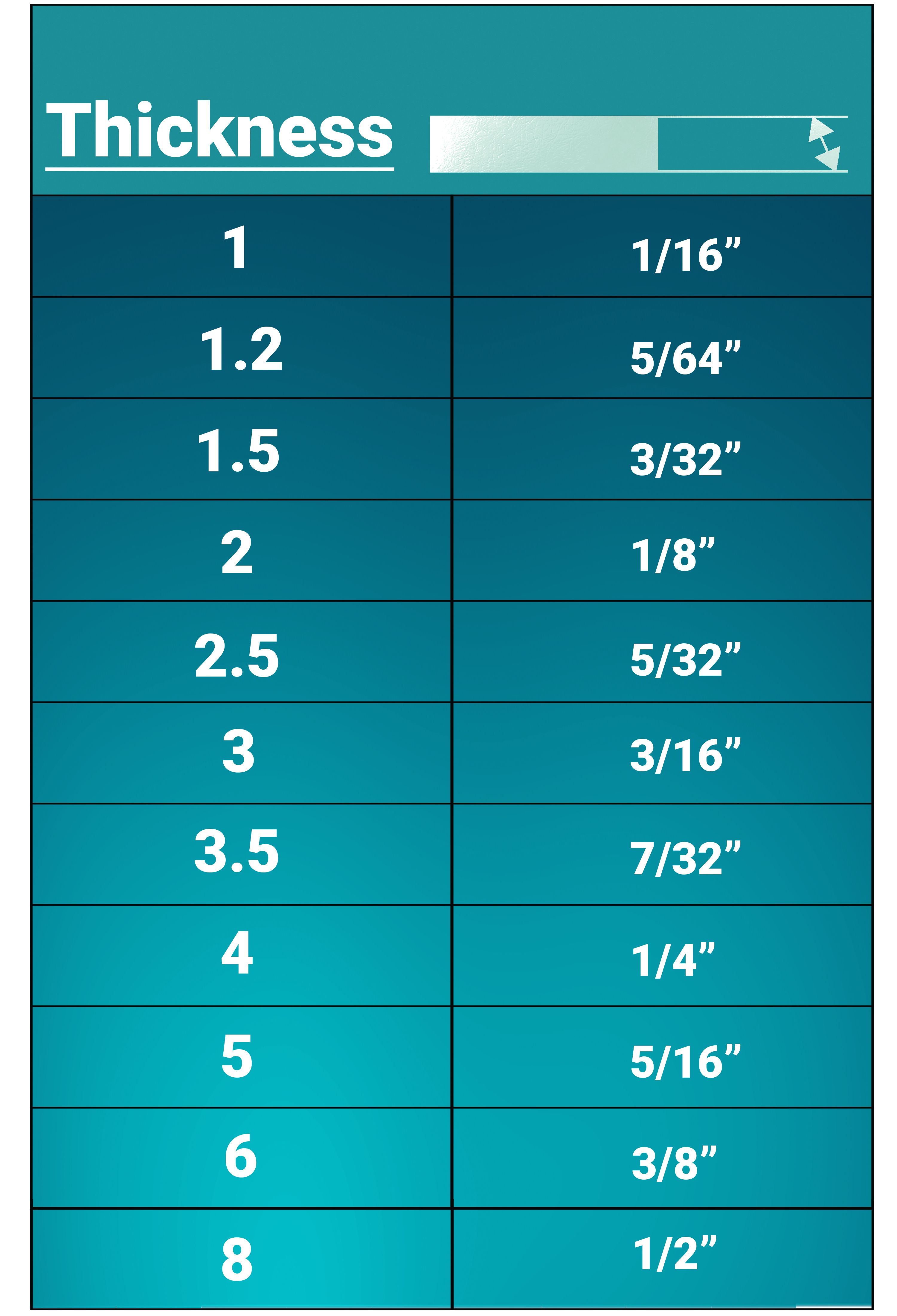
432
The second number indicates the thickness of the insert. In this example, “3” indicates 3/16″ thick.
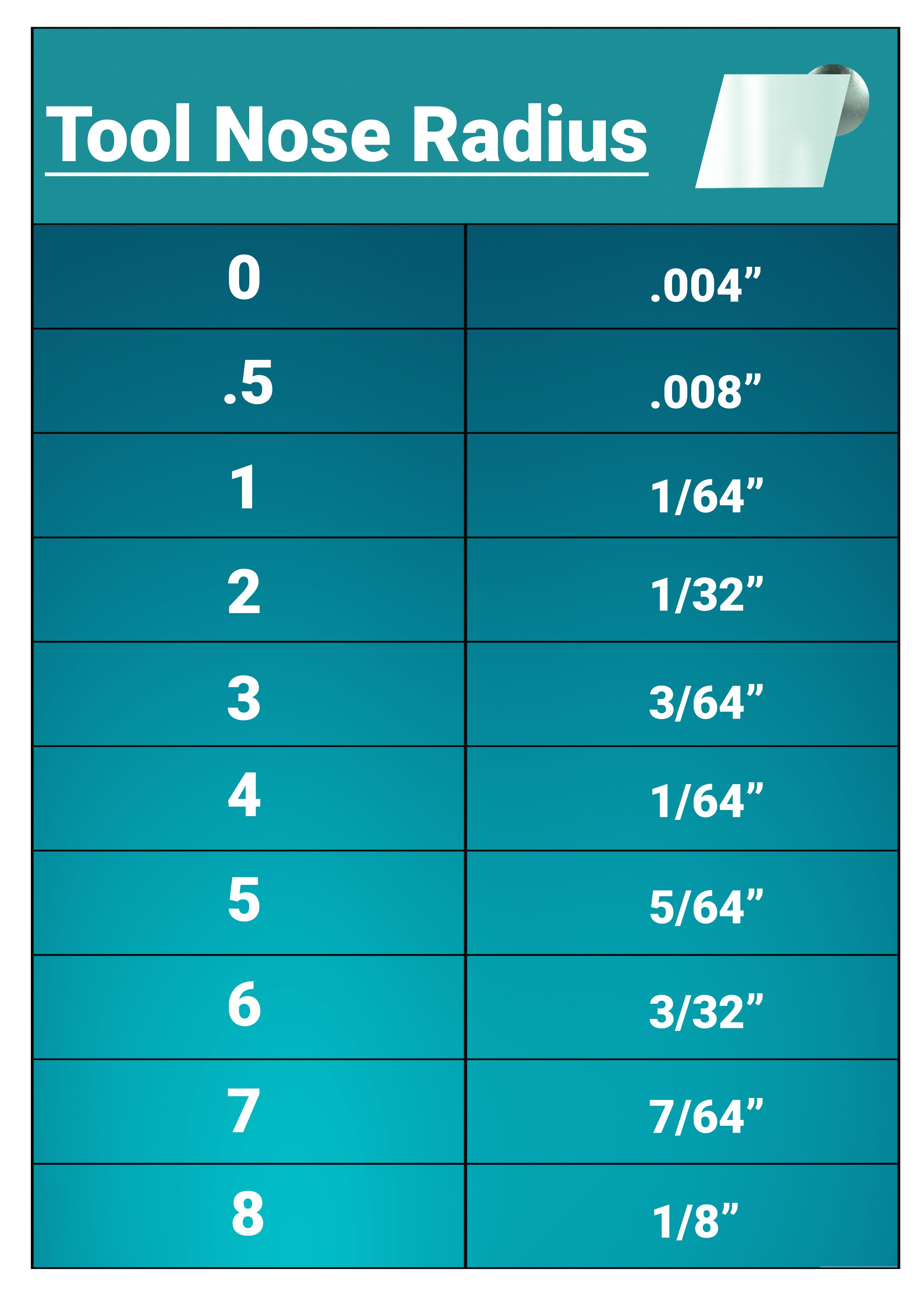
432
The third number indicates the tool nose radius of the insert. In this example, “2” indicates 1/32″(0.031″)
-XX
After the third number is the reserve space for the manufacturer’s chip breaker. Some manufacturers use this space; others do not. It is not limited to two characters. Some manufacturers use combinations of letters and numbers.
*Note tables referencing common are not complete datasets but a listing of commonly used standards.

Author
David Wynn
David Wynn, MBA, is the PMPA Technical Services Manager with over 20 years of experience in the areas of manufacturing, quality, ownership, IT and economics. Email: gro.apmp@nnywd — Website: pmpa.org.