STATE OF MANUFACTURING – Florida Manufacturing

by Joe Jackson

Marketing & Events Assistant, PMPA

Published December 1, 2023

Download Magazine Article

Fabricated Metal Products Manufacturing is a subsector of manufacturing that makes critical goods from metal components.

Precision Turned Products Manufacturing is a subsector of fabricated metal product manufacturing that makes the components that MAKE IT WORK!


FLORIDA ECONOMIC OUTPUT

Florida Manufacturing
NAICS 31-33
$64,480,000,000

Fabricated Metal Product Manufacturing
NAICS 332
$6,954,681,000

Precision Turned Product Manufacturing
NAICS 332721
$235,274,000

FLORIDA MANUFACTURING ACCOUNTS FOR

Manufacturing Is Productivity –4.21% of the Florida total output (GDP)

Manufacturing Builds Businesses –12,418 manufacturing establishments in the state of Florida.

Manufacturing Creates Jobs – 4.33% of all Florida employees are in the manufacturing sector. (388,000 employees)

Manufacturing produces for Florida!

  • Manufacturing is the eighth largest GDP Producer in Florida.
  • Fabricated metals make up 10% of the manufacturing sector in Florida.

Florida is a great place for a career in manufacturing

  • Manufacturing jobs pay on average 19% over the average job in Florida. (according to NAM.org)
  • Florida’s top cities for manufacturing jobs are Jacksonville, Orlando and Miami, collectively combining over 90,000 jobs.


Sources: NAM.org, US Census, Enterpriseminnesota.org, .gov, Statista.com, Axios.com
Data selected to show relative values. May not be directly comparable due to differences in sampling, analysis, or date obtained.


Author

Joe Jackson

Marketing & Events Assistant, PMPA

Email: gro.apmp@noskcajj — Website: pmpa.org.

Roles of Women in Manufacturing Series: What I Learned

Over 20 women were featured in the Roles of Women in Manufacturing series, which started in the January 2023 issue.

by Carli Kistler-Miller

Director of Programs & Marketing, PMPA

Published December 1, 2023

Download Magazine Article


I have been honored to learn about the journeys of over 20 women in the roles of machinist, engineer, human resources, education, quality, owner, marketing, shipping/receiving, management, IT and quality. I learned about many common themes with regard to career paths, advancement and advice.

Career Path

Sixty percent of the women interviewed did not pursue a job in manufacturing at the
start of their careers. Most started without any manufacturing experience and those with experience either found precision machining through a trade school or college degree. Regardless of their start, all of the women interviewed have advanced or are poised to advance in their precision machining companies.

Culture and Mentorship Are the Secret Sauce

When describing their journeys to their current positions, every woman I spoke with mentioned one or two mentors and a company culture which encourages advancement. A common thread amongst the women was an appreciation for the opportunity to learn, and the encouragement they received to pursue new skills and gratitude for advancement paths.

Advice to Women (or Anyone) Seeking a Career in Manufacturing

The sentiment was unanimous. Every woman interviewed encouraged other women to go for it, ignore the old
gender rules and don’t be afraid to try something different. Additionally, they hope women will take advantage of any learning opportunities and ask questions.
These women are proud of their career choice. They are proud of their journey. They are grateful to those who helped or are helping them along the way and encourage others to follow their path. To these incredible women, I say, “Thank you for being an inspiration.”


Author

Carli Kistler-Miller, MBA has over 25 years of experience with
communications, event/meeting planning, marketing, writing and
operations. Email: gro.apmp@rellimc — Website: pmpa.org.

Machining Unleaded Materials —
Reliability is Possible

Leaded steel is no longer produced in the United States.
How do shops approach unleaded brass and steel machining?

by Miles Free III

Director of Industry Affairs, PMPA

Published December 1, 2023

Download Magazine Article

It has been a long time coming, but leaded steel is no longer produced here in the United States. The shutdown of the Republic melt shop in Canton, Ohio, announced in August was the last stand for leaded steel bar production here in the U.S.

Throughout the 1980s and 1990s, as well as the first decade of the ‘00s, various people were predicting the
end of lead in our shops. And customers, particularly
in automotive and in plumbing, started to change their material requirements. Th is was on PMPA’s radar in 2001 and we provided our members with information to help them meet this challenge. Th e year following, Europe began restricting lead with the following: 

• Restriction of Hazardous Substances Directive 2002/95/EC applicable to electrical and electronic equipment was conceived and adopted in February of 2003. Th is first RoHS Directive (ROHS 1) went into effect in 2006.
• Th e Waste Electrical and Electronic Equipment Directive (WEEED) 2002/96/EC also targeted lead in products and the need for recycling.
• Other European directives dealing with lead include End of Life Vehicles (ELV) (2000/53/EC) and the REACH Regulation EC 1907/2006 entered into force in 2007.

All of these made it clear that lead was no longer a “take for granted” ingredient in materials for machining just because it facilitated efficient production in our operations. Th ese described and restricted the conditions for when a lead addition to improve machining may and may not be appropriate in components for various types of products.
Th e bill permitting only the lead-free plumbing components for parts that had been made from leaded brass (AB 1953) was originally passed in 2003 in California and was implemented in 2010. Only parts made from unleaded brass, meeting a 0.25%-maximum-weight lead content, could be sold in California. As the AB 1953 bill clearly states, “Lead leaching into drinking water poses a serious health risk — there is no safe level of lead, according to the Centers for Disease Control and Prevention…” Th e 0.25% lead standard is appropriate for drinking water plumbing. Th e 0.25% standard is supported by scientific studies and major water agencies, and is recognized by the metal manufacturing industry as the standard for “no-lead brass” (link: bit.ly/PMPA-PM1223).

Because of the reduction and elimination of lead in the materials that we machine to make components needed in automotive, electrical and electronic equipment, and potable water/plumbing systems, our shops have had to learn how to machine these new unleaded materials.

At this year’s Horn Technology Days, I was pleased to attend the session “Lead-Free: Machining Brass and Steel with Process Reliability” presented by Ken Hamming from Horn USA. Mattias Luik, manager of research and development, was also present and headed the research project that Hamming was discussing.

The second content slide showed photos of large, tangled birds-nest chips — convincing evidence that the researchers understand the problem that unleaded materials give our machinists. Th e project concentrated on grooving, one situation where the groove dimensions constrain the chip, contributing to the chip evacuation and massing problems we encounter with unleaded materials. What was the primary takeaway from this work? Unleaded brass needs a positive rake angle. Th is is a change from the zero-rake angle typically found on tools for turning leaded brass. Th e Horn work showed examples of different geometries with specific angles and chip control features and were able to show which were the best — those creating small loose arc and elemental chips. They also showed the geometries which resulted in uncontrollable snarled, ribbon and tubular type chips — the chips most of us expect with unleaded materials, requiring frequent shutdowns for chip clearing.

Horn also showed how changing tool geometries were
effective at getting steady state cutting conditions and chip formation in unleaded steels. Unleaded steels continue
to grow in importance in markets served by our precision machining shops. Th is is why improvements in tooling are critical to our success.

If cutting unleaded steels or brasses is part of your business plan, you can be assured that the production of chips from these materials can be controlled with the proper attention to tool geometry, chip control features and rake and clearance angles. I saw it with my own eyes and held the chips in my hand. Here are some major takeaways for our shops when approaching unleaded brass and steel machining: 

• Speeds. Luik says that with today’s coatings and the right tool geometries, increasing speeds is actually possible for unleaded brass.
• Improve tools. Positive rake angles for brass was unexpected. Improved geometries for chip control also make our operations repeatable in unleaded materials.
• Increase coolant and delivery. Especially benefits constrained features such as deep grooves and holes.
• Improve chip control. Th is can create the most stable, consistently controlled, easily removed chips.

So, whether you go to your tool supplier to get the tools specialized for unleaded materials or decide to confront these challenging materials alone, do know that they can be mastered with the chip form controlled by the criteria discussed above. And I was absolutely amazed when I saw those loose arc and elemental chips coming off a grooving tool in a narrow groove being formed in unleaded brass.

The times, they are finally changing. Fortunately, so is the technology to master these changes.


Author

Miles Free III is the PMPA Director of Industry Affairs with over 50 years of experience in the areas of manufacturing, quality and steelmaking. Miles’ podcast is at pmpa.org/podcast. Email Miles


PMPA Craftsman Cribsheet #121:
ISO Turning — What Does it All Mean?

How to make sense of all those different letters and numbers in ISO turning inserts.

Published November 1, 2023

By David Wynn, Technical Services Manager, PMPA

Download Magazine Article


When it comes to ISO turning inserts, there is a lot of confusion about what all those different letters and numbers mean.  We have CNMG, TNMG and WNMG.  Then there is 432, 332, 434 and more. Even among those who deal with ISO turning inserts everyday, few know what all the different characters mean in relation to the insert. Also, we find that metric and inch standards differ. We discuss inch inserts in this article. Let’s use a CNMG 432 as an example.

CNMG
The first letter denotes the shape of the insert. Inserts come in a wide variety of shapes. In this example, “C” is an 80-degree rhombic shape. Other common shapes used in everyday machining include “T” Triangle, “W” Trigon and “V” 35-degrees rhombic.

A chart showig common shapes

CNMG
The second letter denotes relief angle. “N” in our example is a 0-degree relief angle. Angles can range from 3-degrees to 30-degrees on standards.  Then there is the “O” designation or special angles. For front relief, “C” (7-degrees) is a good common angle for most materials. Some copper grades like to have a little more.

A chart showing relief angles.

CNMG
The third letter denotes tolerance level of the insert. The letter “m” is the tolerance of the cutting tip to the inscribed circle. “T” is the insert thickness tolerance.  The letter “d” represents the inscribed circle tolerance. “M” is a common tolerance class. “G” is also a common tolerance class, but it comes at a higher cost per insert because of the much better tolerances.

A chart showing common tolerances

CNMG
The fourth letter denotes fixing and chip breaking. “G” is put in with a screw with no special chamfers on the insert.   The chip breaking part was a good idea, but in practice does not really matter.  

Most manufacturers make custom or patented chip breakers that have nothing to do with this designation. This letter usually only indicates how the insert attaches to the holder and the back rake design.
 
The Numbers
432
The first number denotes the inscribed circle of the insert.  In the example, “4” indicates a 1/2″ inscribed circle.

A chart showing inscribed circle measurements

432
The second number indicates the thickness of the insert.  In this example, “3” indicates 3/16″ thick.

A chart showing thickness measurements

432
The third number indicates the tool nose radius of the insert. In this example, “2” indicates 1/32″(0.031″)

A chart showing tool nose radius measurements

-XX
After the third number is the reserve space for the manufacturer’s chip breaker. Some manufacturers use this space; others do not. It is not limited to two characters.  Some manufacturers use combinations of letters and numbers.

*Note tables referencing common are not complete datasets but a listing of commonly used standards.


Author

David Wynn

David Wynn, MBA, is the PMPA Technical Services Manager with over 20 years of experience in the areas of manufacturing, quality, ownership, IT and economics. Email: gro.apmp@nnywd — Website: pmpa.org.

STATE OF MANUFACTURING – Minnesota Manufacturing

by Joe Jackson

Marketing & Events Assistant, PMPA

Published November 1, 2023

Download Magazine Article

Fabricated Metal Products Manufacturing is a subsector of manufacturing that makes critical goods from metal components.

Precision Turned Products Manufacturing is a subsector of fabricated metal product manufacturing that makes the components that MAKE IT WORK!


MINNESOTA ECONOMIC OUTPUT

Minnesota Manufacturing
NAICS 31-33
$53,130,000,000

Fabricated Metal Product Manufacturing
NAICS 332
$10,055,374,000

Precision Turned Product Manufacturing
NAICS 332721
$947,485,000

MINNESOTA MANUFACTURING ACCOUNTS FOR

Manufacturing Is Productivity –13.63% of the Minnesota total output (GDP)

Manufacturing Builds Businesses –6,387 manufacturing establishments in the state of Minnesota.

Manufacturing Creates Jobs – 11% of all Minnesota employees are in the manufacturing sector. (320,000 employees)
Minnesota created 64,000 new manufacturing jobs from January 2021 to May 2023, a 5.3% invrease which outpaced most of the Midwest states.


Manufacturing produces for Minnesota!

  • Manufacturing is the largest contributor to Minnesota’s economic output.
  • Fabricated metals is the fifth largest manufacturing sector in Minnesota.

Minnesota is a great place for a career in manufacturing

  • Manufacturing jobs pay on average 28% over the average job in Minnesota. (according to NAM.org)
  • 20% of Minnesota’s manufacturing jobs are located in the southern region of Minnesota (Renfield, Chippewa area).


Sources: NAM.org, US Census, Enterpriseminnesota.org, .gov, Statista.com, Axios.com
Data selected to show relative values. May not be directly comparable due to differences in sampling, analysis, or date obtained.


Author

Joe Jackson

Marketing & Events Assistant, PMPA

Email: gro.apmp@noskcajj — Website: pmpa.org.

Roles of Women in Manufacturing Series: Shipping/Receiving in Manufacturing: Yahaira Bermudez, Ramona Campbell and Elizabeth Colin

Three women share their journeys to shipping/receiving in manufacturing, and give advice to anyone seeking a career in manufacturing.

by Carli Kistler-Miller

Director of Programs & Marketing, PMPA

Published November 1, 2023

Download Magazine Article


You can’t make the parts without bringing in the materials and tools, and you can’t make money on the parts without shipping them. Our shop’s shipping and receiving departments are critical to success.  

Yahaira Bermudez’s Journey
Walk into the shipping and receiving department of Somma Tool in Waterbury, Connecticut, and you’ll find Yahaira Bermudez picking and packing for orders, receiving and examining incoming shipments and assisting in some production. She tested different trades in high school and fell in love with precision machining.  She took the job at Somma Tool, likes the paperwork process and working with computers. Plus, Somma is training her for her dream job of machine operator and programmer.

Ramona Campbell’s Journey
Ramona Campbell serves as the shipping specialist at Precision Plus in Elkhorn, Wisconsin. She makes sure all the shipments are correct and sent with the proper paperwork. She enjoys that she can see all the different parts and appreciates that Precision Plus is allowing her to grow her skills.


Elizabeth Colin’s Journey

Elizabeth Collin was skeptical about taking the shipping and receiving position at Precision Plus in Elkhorn, Wisconsin, thinking that might not be the career path she wanted. But it turned out to be a great decision, because she now has shipping management duties and serves as the puchasing specialist assistant. She loves the opportunities afforded her in manufacturing.

Advice to Women (or Anyone) Seeking a Career in Manufacturing
When asked for advice for women — or anyone — seeking a fulfilling career, Yahaira states, “Gender should not define what your qualities are in this industry. You’re just as qualified as any other person in this role.” Ramona shares, “Don’t be afraid. Give it a try, especially when you like working with people is a good place to be.” And Elizabeth says, “Stop stereotyping yourself and instead seek adventure with new possibilities. Never be afraid and be open to challenges.”


Author

Carli Kistler-Miller, MBA has over 25 years of experience with
communications, event/meeting planning, marketing, writing and
operations. Email: gro.apmp@rellimc — Website: pmpa.org.

One Sign to Rule Them All

It is possible that one sign holds the key to understanding a shop’s culture and performance.

by Miles Free III

Director of Industry Affairs, PMPA

Published November 1, 2023

Download Magazine Article

As an experienced manufacturing “hand” I am always looking for proxy indicators, cognitive shortcuts or clues that give me deeper insights into the complexity that is our precision machining manufacturing operations.
While on PMPA’s Mastery tour, I came across just such a proxy indicator and was impressed at how thoroughly it was validated across the entire shop and operations.

With permission from our host, I am sharing my lesson learned and introducing the latest proxy indicator: the one sign that rules them all.

The idea for the “One Sign To Rule Them All” is reminiscent of the “One Ring That Rules Them All”  from “The Lord of the Rings” trilogy. There is magical power in the rings, and there is more powerful magic in the one ring that rules them all. On our visit to AccuRounds in Avon, Massachusetts, I saw a sign and its power was compelling to me — everywhere I looked, I saw visually that this sign was the dominant and controlling influence in the operations.

What did the sign say? Wherein did it get its great power? The sign said FOD Awareness Area.

That’s it. Three words. But so much power.

In order to  understand its magical power, it is important that we understand what exactly is meant by  “FOD”?

The Federal Aviation Administration  defines FOD in  AC 150/5210-24, Airport Foreign Object Debris (FOD) Management, as “…any object, live or not, located in an inappropriate location in the airport environment that has the capacity to injure airport or air carrier personnel and damage aircraft.

“The presence of FOD is a continuing concern at our nation’s airports. FOD creates safety hazards and can ultimately impact safe operations by damaging aircraft. Airports, Airlines, and the General Aviation community have taken the necessary steps to minimize FOD by engaging in successful FOD management programs, as per AC 150/5210-24.”

Substitute the word “manufacturing” for “airport” and  “air carrier,”  and “machinery and equipment” and “machine tools” for “aircraft” and you have the manufacturing definition of FOD.

Our shops historically  have used the term “housekeeping,” OSHA 1910.22 uses “walking working surfaces,” and lately many of our shops have employed 5-S  to mean the same thing — essentially, in simplified terms — a place for everything, and everything in its place.

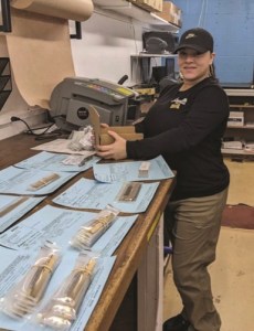
So why do I give this FOD sign such respect? Pictured to the right is the area where this shop processes the swarf (oil contaminated chips) from their operations.

Spotless. Chipless. Immaculate. And this was during operations! We watched the processing of several carts of chips and the area remained — dare I say — “pharmaceutical quality” in regards to housekeeping.

And so it was, everywhere else in the shop. No extraneous materials, blocking, banding or even oil drops on the floor. What is the magic, the power behind FOD? What gives the three words on this sign so much power?  There are many reasons that we could consider, but I suggest that the power lies in our enlightened self-interest and our desire for our own well-being as well as that of our colleagues.

What is FOD?  “…any object…located in an inappropriate location… that has the capacity to injure… personnel and damage.” There is the power. Our realization that FOD is our opponent. It is the villain that can take away our safety.

FOD is a grave danger, and a totally needless one. Uncontrolled, FOD has the ability to injure us on the job or damage our equipment that is the means of our livelihood, and possibly interrupt our service to our customer, potentially causing loss of business.

This one sign gets its power to rule them all, because following it promises to intelligently manage risk to us, to our coworkers and to our equipment and business.

Companies post their Vision, Mission and Purpose statements  to help them communicate their intentions, their reason for being.  And these are often up to the task.

But sometimes, these are not sufficient to the task of describing how it is that the company works, nor at describing what sets them apart. On our visit to the AccuRounds on PMPA’s latest Mastery program tour, I found a proxy indicator, a sign, that made everything visible to me.

What will I find in your shop?


Author

Miles Free III is the PMPA Director of Industry Affairs with over 50 years of experience in the areas of manufacturing, quality and steelmaking. Miles’ podcast is at pmpa.org/podcast. Email Miles


Precision Ground Barstock: How It Is Manufactured, Benefits to Your Shop

Understanding the benefits provided by precision centerless ground barstock can help you avoid false economy and optimize the work you quote by maximizing benefits to your manufacturing process and customer.

by Miles Free III

Director of Industry Affairs, PMPA

Published April 1, 2023

How Are Bars Centerless Ground?

In centerless grinding machines, a prepared bar is supported over its length and fed into a gap between an abrasive (grinding) wheel and another rubber wheel which presses the bar into the abrasive wheel and, as it spins the bar, the bar advances forward. The amount of stock removal is determined by the force applied by the rubber wheel. Multiple passes may be needed to achieve the final size, and a final pass may take a minimum amount of removal.

Why Centerless Bar Grinding?

Grinding — in particular, centerless bar grinding — is employed when very close tolerances or a very smooth surface finish is needed for an application. There are other reasons to choose precision ground bars in our shops. Precision ground bars are specified in ASTM A 108 Steel Bar, Carbon and Alloy, Cold-Finished. Size tolerances for Level 2 and Level 3 cold-finished round bars cold drawn, ground and polished, or turned, ground and polished can be found in Table A1.3 of ASTM A108. Tolerances are based on bar diameter and are unilateral (to the minus only) from the specified size. Out-of-roundness in these products is “as agreed” between supplier and customer. Note: Unlike Level 1 cold-finished alloy steel bars, cold drawn or turned and polished, the tolerance for centerless ground bars is not determined in part by carbon content or prior thermal treatments.

  • The reasons to select a precision ground bar are few but compelling:
  • The customer requires a demanding surface finish (Ra).
  • The customer needs the very limited size tolerance.
  • The customer’s equipment requires high precision feedstock.
  • It adds additional assurance that the material is seam-free.
  • Length tolerances are held to a tighter range.
  • Material may be in stock available for prompt delivery.

The customer requires a demanding surface finish (Ra).
For Level 1 ground and polished, an (Ra) of 40 microinches max may be specified. For Level 2, an (Ra) max of 30 microinches is specifiable, according to Table A 1.7; for Level 3, a 20 microinches max (Ra) is given. Note: Special
surface (Ra) restrictions must be agreed upon at time of inquiry — even more restrictive finishes may be available,
depending upon additional passes or processes being employed.

The customer needs the very limited size tolerance.

Depending on the nominal diameter — for example 1 inch — the size tolerance of the Level 3 ground bar could be as little as 0.0008″ compared to a Level 2 tolerance of just 0.001″. For carbon grades, supplied as cut lengths, the Level 1 tolerance as cold drawn or turned and polished could range from 0.002 to 0.005 inches, all tolerance minus depending on diameter. For this example, we are using under 1-1/2″. For alloy grades, Level 1 (cold drawn only or turned and polished) supplied as cut lengths, the tolerance could range from 0.003″ for low carbon grades up to as high as 0.006″ for maximum of carbon range over 0.55%, regardless of stress relief or annealing prior or after cold finishing, as well as all carbon levels quench and tempered or normalized and tempered. (All tolerance is minus.) The maximum allowable departure from roundness (out of round or maximum ovality) is as agreed between the supplier and the customer. For very challenging parts, if the OD of the bar is going to be used in the customer’s finished part, the centerless grinding process can deliver the tightest dimensional compliance of all available cold finishing processes.

The customer’s equipment requires high precision feedstock. 

Certain types of machining processes can benefit greatly from utilizing precision ground barstock, such as CNC Swiss-type screw machining. In these instances, there are a myriad reasons for requiring ground material not detailed in this article..

It adds additional assurance the material is seam-free.

Grinding and polishing takes a  nal additional stock removal that can help ensure that the material is seamfree (surface imperfection free.)  is can be part of the normal stock removal calculation or can be additional to the removal taken prior to the grinding process to provide additional assurance. Consult with your supplier to understand the stock removal and its warranty regarding surface imperfections.

Length tolerances are held to a tighter range.

(All tolerance is plus for length.) For Level 2 and Level 3, cold finished steel bar is held to tighter range (1 inch for Level 2; half an inch for Level 3, compared to 2 inches for Level 1 product.)


Material may be in stock available for prompt delivery.

Finally, a less important — but often overlooked factor — is that the bar grinder may actually have material in stock available for prompt delivery. Sometimes the quantity on hand may be sufficient for a small job in our shops. The
advantage of this factor, though, is attributable more to the availability/stocking position than to any technical

attributes imparted by the precision grinding. Often, the ground finish and precision may be overkill for a job, but the only material that can be found is available at the bar grinder. The reasons arguing against the use of precision ground barstock include higher cost per pound than other cold-finished steel bar products, and perishability of finish. The higher cost of precision ground bars is not just because of the cost of the grinding operation, it is also attributable to the yield
loss of material removed during the grinding process. The fine finish imparted by the centerless grinding operation can be defeated by mishandling — scratches, dings and other abrasions can render the material unit for the most demanding
applications. Handle with care! There are a number of reasons for choosing centerless ground barstock to ensure both shop productivity and that your process delivers the highest quality to your customers.


Author

Miles Free III is the PMPA Director of Industry Affairs with over 50 years of experience in the areas of manufacturing, quality and steelmaking. Miles’ podcast is at pmpa.org/podcast. Email Miles

Factors Influencing Machined Surface Finish in Our Shops

Surface finish is the result of our machining process on raw materials.

Published March 1, 2023

There are three principal causes of surface roughness:

  • the feed marks left by the tool on the work;
  • fragments of built-up edge (BUE) pressed into the surface of the work by the tool during chip formation and removal;
  • artifacts resulting from tool vibration and displacement on the workpiece. Efforts to reduce the height (depth) of the feed (tool marks), reduce the size of BUE, and reducing vibration by improving rigidity will improve as machined surface finish.

Here are some of the various factors that can impact surface finishes produced by our machining processes.

Material Factors

High hardness, high strength, and low ductility tend to be associated with good surface finish in steels. Lower carbon steels tend to be lower hardness and lower strength, more ductile, and thus tend to leave a more torn surface finish. Higher carbon steels cut more crisply than low carbon grades, which are more suited for cold heading.
The strain hardening of hot rolled steels by cold drawing has been shown to improve as machined surface finish.
In addition to mechanical properties and treatments, chemical composition can also contribute to improved machined surface finish — increasing carbon content improves surface finish compared to low carbon steels.
Free machining additives such as sulfur help to control built-up edge, resulting in improved finishes. Additions of phosphorus and nitrogen can help embrittle the chip, contributing to smother finishes. Lead, as well as selenium, tellurium and bismuth also help with chip separation, improving surface finish off the machine.

Machining Factors

While specifying chemistry remains out of our scope in most contract manufacturing, the machinist has several variables that are under their control.
Cutting speed has probably the largest potential to improve machined surface finish as anything else we can do in our shops. Increasing cutting speed greatly improves surface finish achieved. Increasing feed significantly reduces surface finish, so increasing speed while reducing feed is a likely path to improving surface finish in a new job.
Increasing rake angle also leads to significant improvement in surface finish. While many shops have moved from HSS tools of their own manufacturer to the use of premanufactured inserts, knowing what the angles do for surface finish can help you when trying to move to another insert to improve finish.
Increasing relief angle can reduce surface finish, while increasing side cutting edge angle is usually associated with improved surface finish. Increasing the end cutting edge angle can lead to large declines in surface finish.
Increasing the nose radius of the tool, can improve surface finish, as long as the grade does not easily work harden. (Most nickel grades work harden). Increasing the nose radius of the tool reduces the depth or height of the tool ridges left by the tool. Larger nose radius also reduces the size of the chip as well as the BUE.
Tool materials, tool coatings, metalworking fluids, and additives also have a role to play in improving machined surface finishes in our shops. However, the precision machinist has several options in their control: increasing speeds, reducing feeds, increasing angle of cut and increasing nose radius.


Access to All PMPA Cribsheets

Access to PMPA Knowledge Centers


  •  

STATE OF MANUFACTURING – California Manufacturing

by Joe Jackson

Marketing & Events Assistant, PMPA

Published March 1, 2023

Fabricated Metal Products Manufacturing is a subsector of manufacturing that makes critical goods from metal components.

Precision Turned Products Manufacturing is a subsector of fabricated metal product manufacturing that makes the components that MAKE IT WORK!


Annual Economic Output

California Manufacturing
NAICS 31-33
$324,430,000,000

Fabricated Metal Product Manufacturing
NAICS 332
$28,829,805,000

Precision Turned Product Manufacturing
NACIS 332721
$1,483,765,000

CALIFORNIA MANUFACTURING ACCOUNTS FOR

Manufacturing Is Productivity – 10.36% of California’s total economic output

Manufacturing Builds Businesses 24,304 – manufacturing establishments in the state of California

Manufacturing Creates Jobs – 8% of the all California employees are in the manufacturing sector. (1.5 million employees)

Manufacturing Earns Export Dollars – California manufactured goods exports were valued at $133.75 Billion.

Manufacturing is Impact – California accounts for 14.5% of the U.S. total manufacturing output.


Manufacturing produces for California!

  • Manufacturing is the 2nd largest industry 
  • Manufacturing is the 2nd largest source of GDP in California.
  • Manufacturing is a major source of growth in California. In 2021, they recorded a 17% job growth rate in the manufacturing sector alone.


California is a great place for a manufacturing career.

  • Manufacturing jobs pay on average 24% over the average jobs in California with an average salary of $112,381 per year.

Sources: NAM.org, IndustrySelect.com, US Census, CA.gov, Statista.com

Data selected to show relative values. May not be directly comparable due to differences in sampling, analysis, or date obtained.


Download Magazine Article


Author

Joe Jackson

Marketing & Events Assistant, PMPA

Email: gro.apmp@noskcajj — Website: pmpa.org.